 ×
×

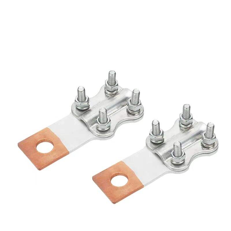
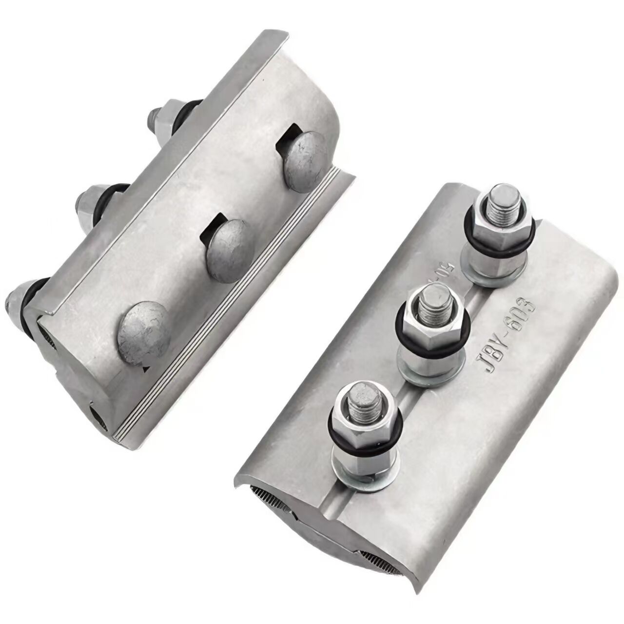
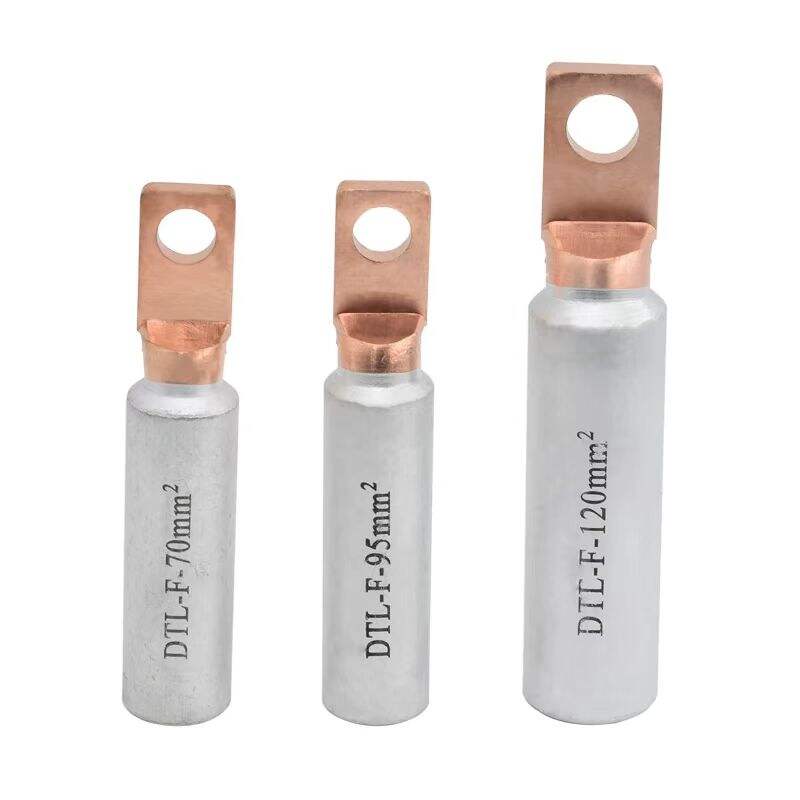
1. Bi-Material Composite
Manufactured using copper-aluminum composite material, combining copper's superior conductivity with aluminum's cost-effectiveness and lightweight advantages.
2. Optimized Structural Design
Features a semi-circular arc structure at the conductor connection point to ensure maximum surface contact and secure clamping, preventing conductor creep.
Available in multiple configurations (0°, 30°, etc.) to accommodate different angles between the downlead and equipment terminal.
3. Advanced Manufacturing Process
Produced through precision stamping for single-step forming, requiring no additional post-processing. Ensures consistent product quality and reliable performance.
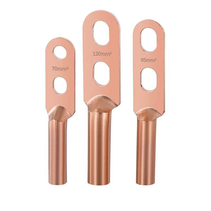
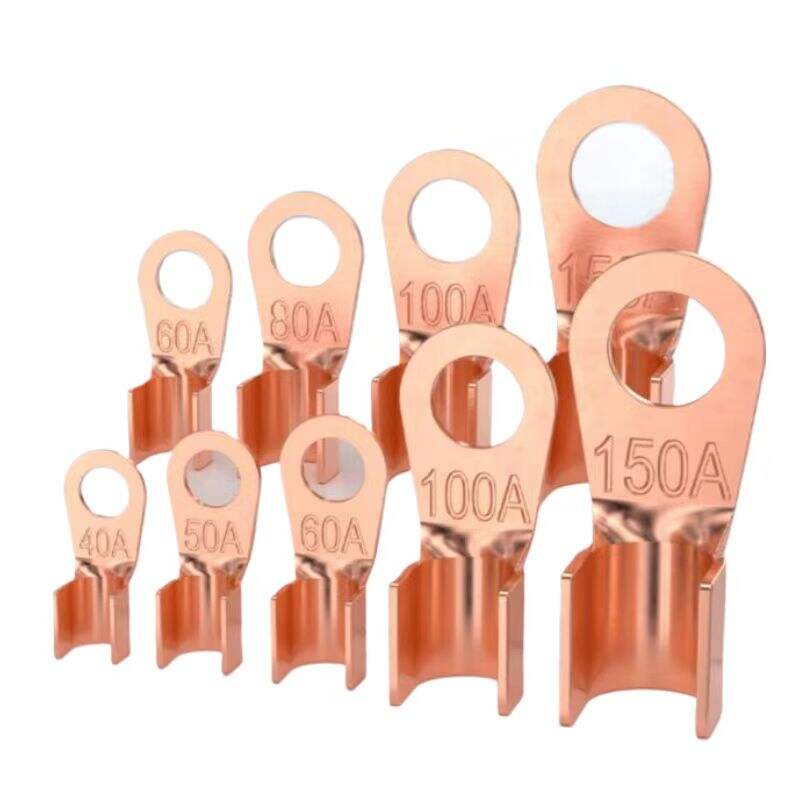
1. Excellent Electrical Performance
Low contact resistance and high conductivity minimize power loss and heat generation.
Ensures stable current transmission with reliable, long-term connections.
2. Superior Corrosion Resistance
Optional tin-plated surface treatment enhances resistance to oxidation, ideal for harsh environments (coastal, industrial, or polluted areas).
Extended service life with durable material composition.
3. Quick and Easy Installation
Bolt-fastened design: Simply place the bare conductor in the semi-circular groove and tighten the bolt.
Self-aligning feature automatically centers the conductor for precise positioning.
Simplified operation with no loose parts, reducing installation time and errors.
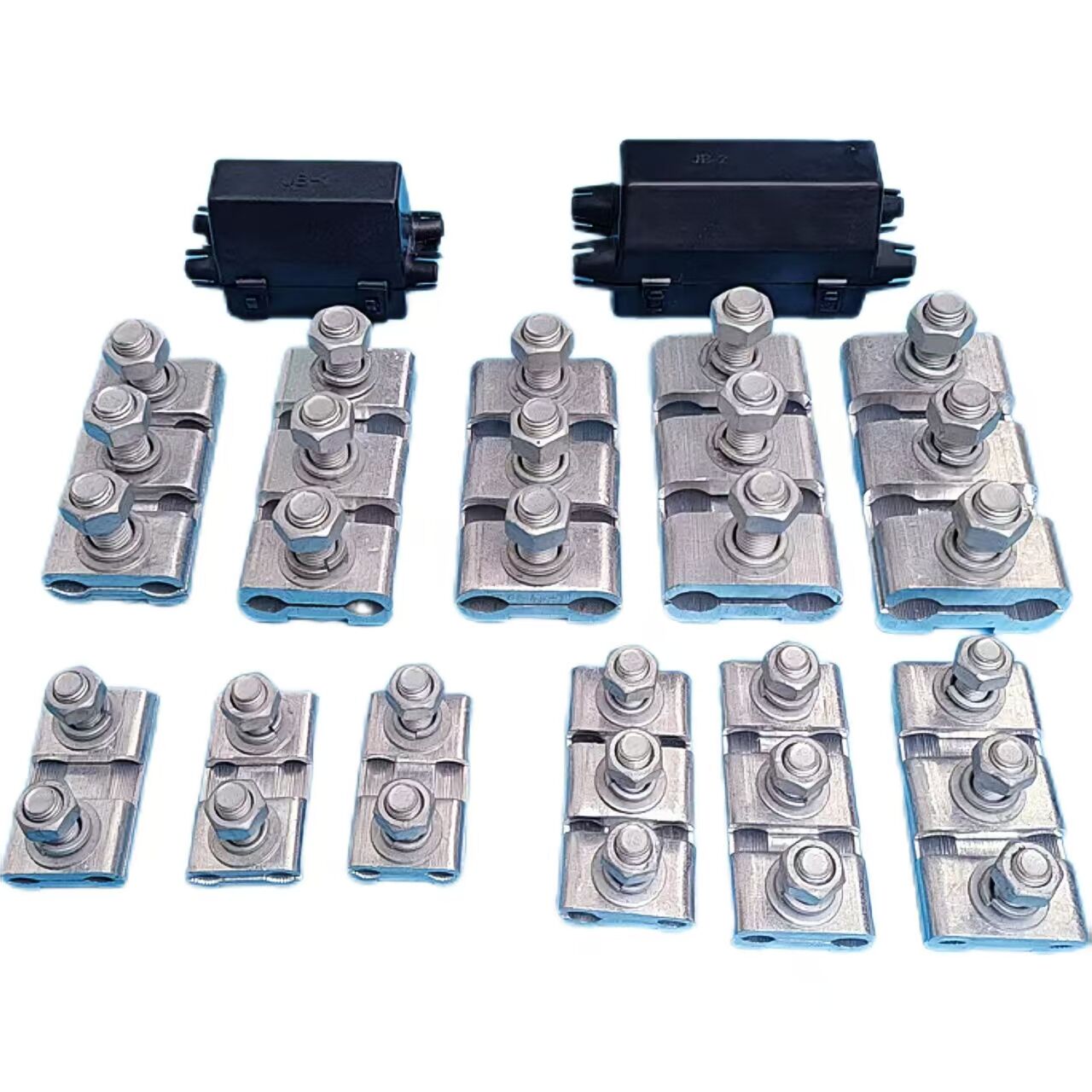
1. Electrical Connection Functionality
Primarily designed for connecting busbar downleads to electrical equipment terminals (transformers, circuit breakers, current transformers, disconnect switches, etc.)
Ensures reliable electrical connection between copper and aluminum conductors
Facilitates uninterrupted current flow in power transmission systems.
2. Mechanical Fixation Capability
Provides robust mechanical support for conductors
Securely fastens conductors to electrical equipment
Withstands mechanical stresses including conductor tension
Maintains stable line connections under various operational conditions.Alternative technical expressions
For electrical connection: "Establishes low-resistance interface between dissimilar conductors"
For mechanical fixation: "Engineered to withstand dynamic loads and vibration
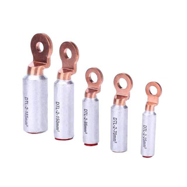
| Model | Applicable wire(m㎡) | Main dimensions(mm) | ||||||
| Φ | L | L1 | W | A | A1 | A2 | ||
| JTL-100A | 16~25 | 10.5 | 76 | 40 | 23 | 3.2 | 2.7 | 3.5 |
| JTL-200A | 25~35 | 12.5 | 85 | 52 | 25 | 4.0 | 3.0 | 4.0 |
| JTL-300A | 35~50 | 12.5 | 95 | 58 | 29 | 4.2 | 3.5 | 4.5 |
| JTL-400A | 50~70 | 12.5 | 104 | 61 | 31 | 4.2 | 3.5 | 4.5 |
| JTL-500A | 70~95 | 14.5 | 109 | 68 | 33 | 4.5 | 4.0 | 5.0 |
| JTL-600A | 95~120 | 14.5 | 114 | 68 | 35 | 4.5 | 4.0 | 5.0 |
| JTL-800A | 120~150 | 14.5 | 125 | 75 | 35 | 5.0 | 4.0 | 5.5 |
| JTL-1000A | 150~185 | 14.5 | 136 | 75 | 40 | 5.0 | 4.5 | 6.0 |
| In the table, AI represents the thickness of the JT series copper wiring clips, and A2 represents the thickness of the JL series aluminum wiring clips. Other dimensions of JT and JL are the same as those of JTL in the above table. | ||||||||
Our professional sales team are waiting for your consultation.
 E-mail: