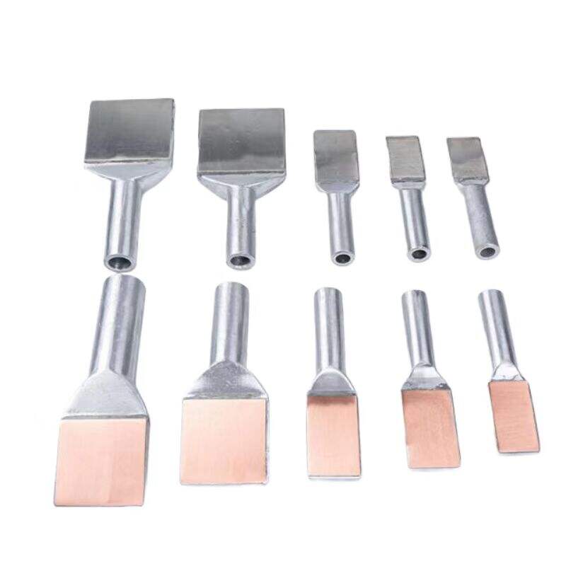
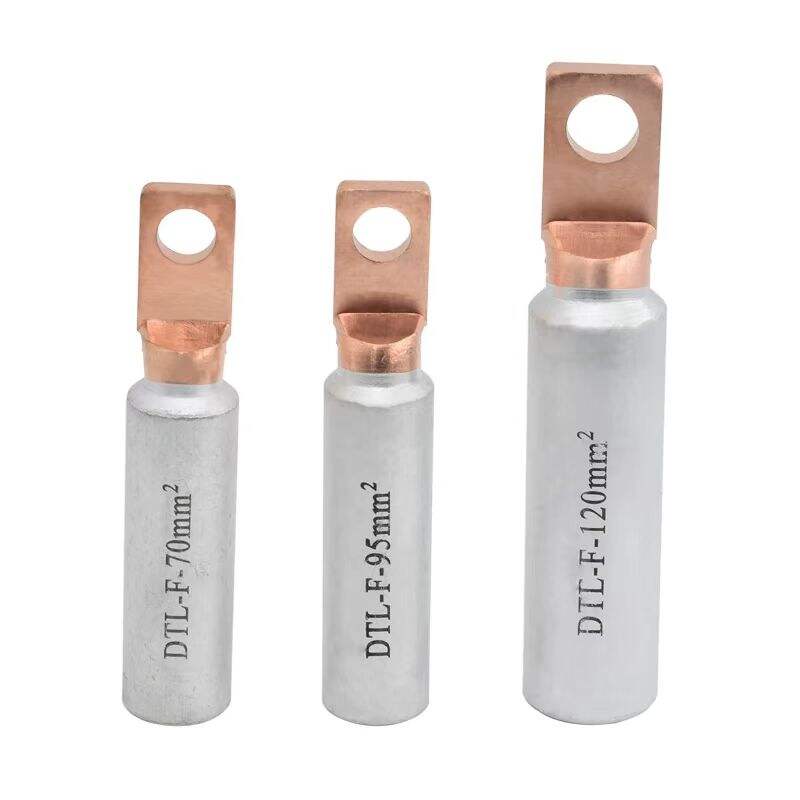
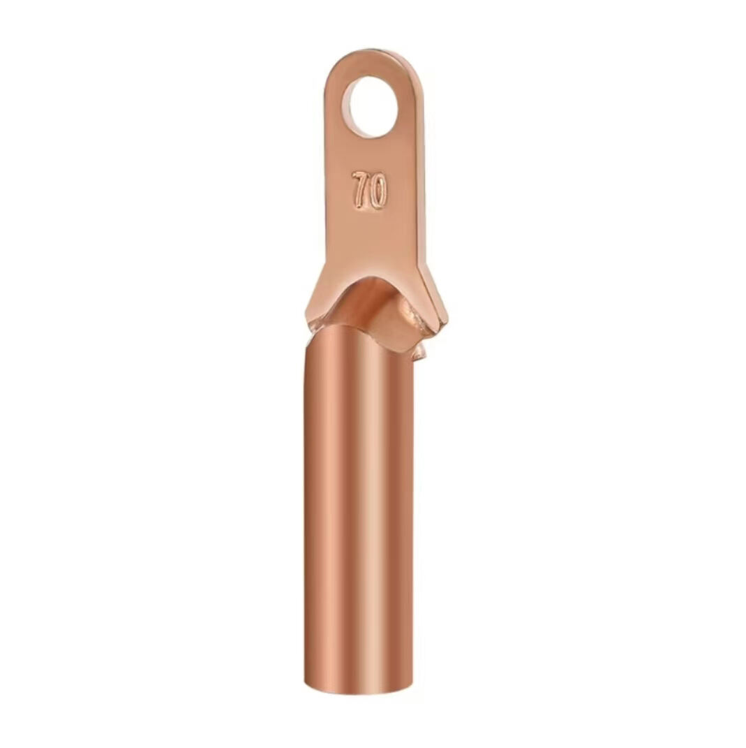
1. Material Combination
Constructed from copper and aluminum, connected via brazing technology, integrating copper’s excellent electrical conductivity with aluminum’s advantages of light weight and low cost.
2. Process Advantages
The brazing process ensures a tight bond between copper and aluminum, with a dense texture and high strength. This avoids defects such as internal looseness, sand holes, and slag inclusions that may occur in casting processes, reducing risks of crimp cracking and poor contact.
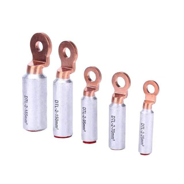
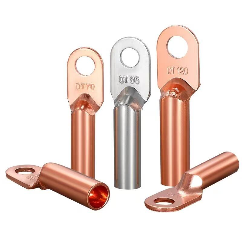
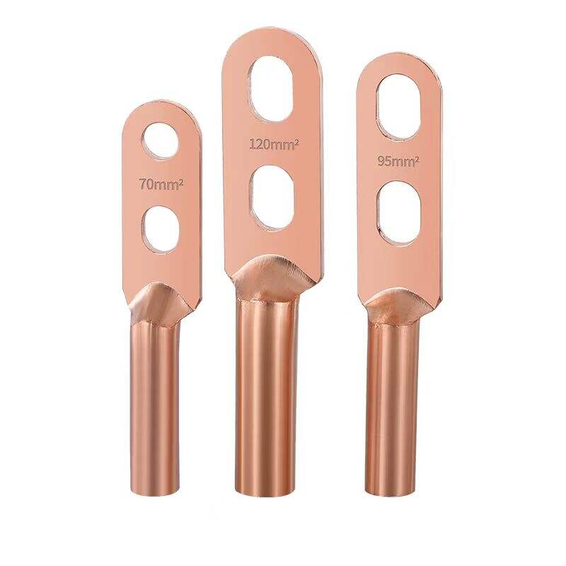
3. Diverse Specifications
Available in multiple specifications, such as SYG-35, SYG-70, SYG-120, etc., to meet the requirements of different current and voltage levels.
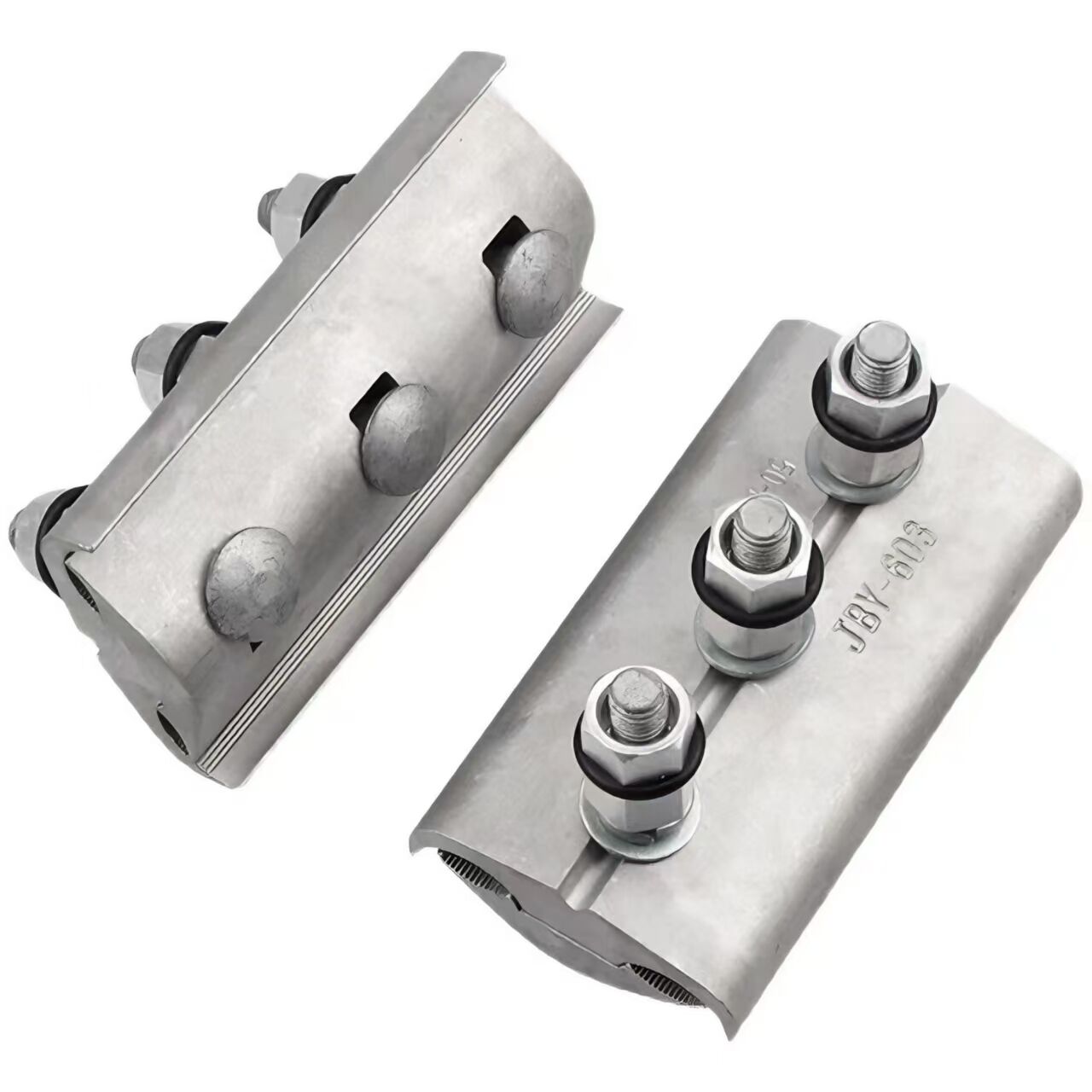
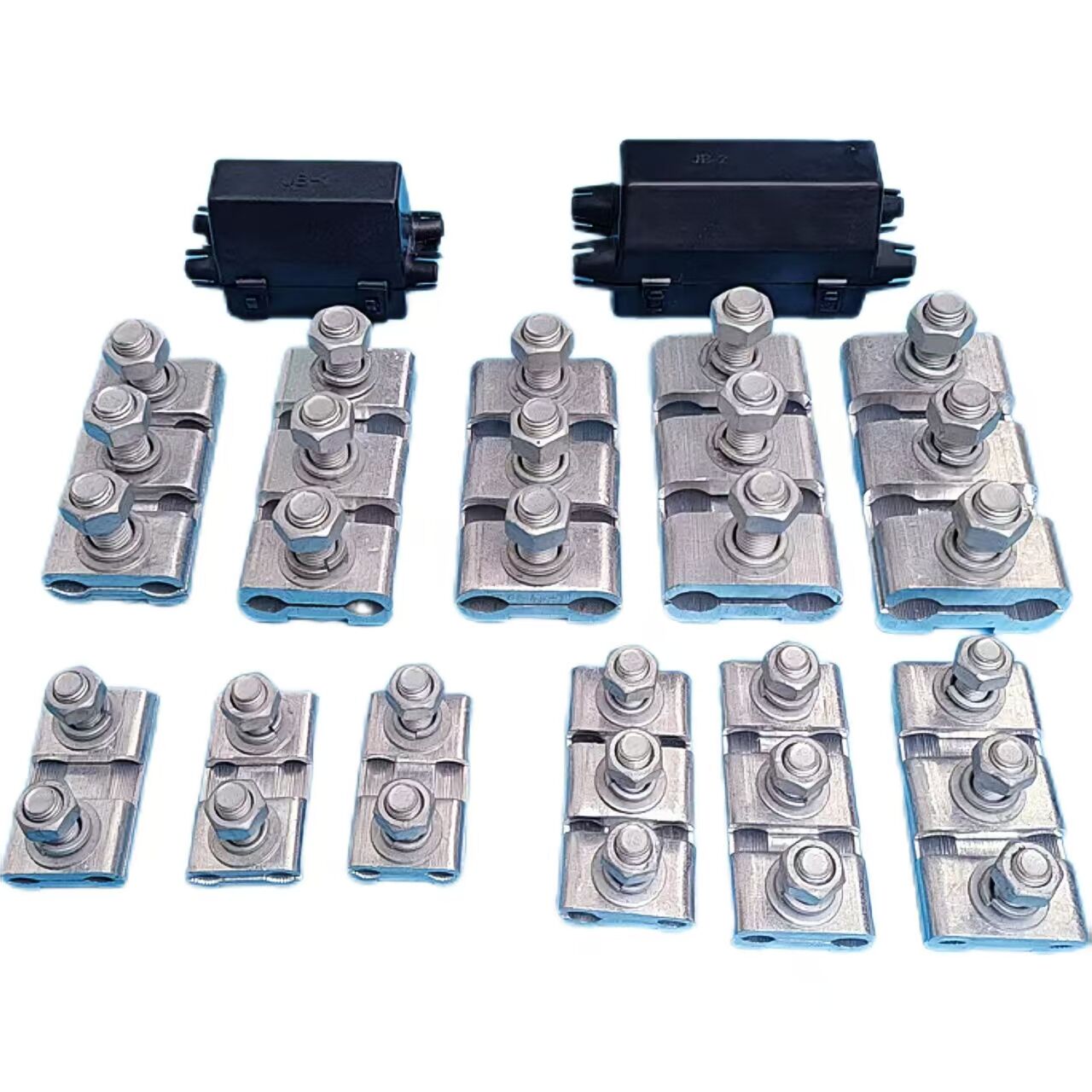
4. Structural Design
The outlet part features a semi-circular arc structure, ensuring large-area contact and a tight grip on the conductor to prevent creep. During installation, it automatically aligns the center position of the bare conductor.
1. Good Electrical Performance
The brazed joint has good electrical and thermal conductivity, which can effectively reduce the contact resistance, reduce power loss and heat generation, ensure good electrical contact performance, and is suitable for permanent connection.
2. Reliable Mechanical Strength
Adopting the forging process of extruded aluminum rods, it has a dense texture and high strength, can withstand various harsh environments, and can bear a certain amount of tensile force and mechanical stress, ensuring the safe operation of the power grid.
3. Strong Corrosion Resistance
In order to improve corrosion resistance, the copper - coated part is usually fully tinned, which can effectively resist the erosion of the external environment and extend the service life.
1. Electrical Connection
Mainly used for connecting the outgoing terminals of substation busbar down-leads with electrical equipment (such as transformers, circuit breakers, disconnectors, wall bushing insulators, etc.), achieving reliable electrical connections between equipment and ensuring the continuity and safety of power transmission.
2. Adaptability to Different Conductors
Suitable for connecting steel-core aluminum stranded wires to copper terminal boards of electrical equipment. It is not only applicable to conventional conductors but also to other conductors within the diameter range of the equipment clamp, offering strong versatility.
Model | Applicable wire models | All size unit are mm | ReferenceWeight(kg) | |||||
A | B | D | L1 | L2 | SY | SYG | ||
SY (G)-120/7NA(B) | NRLH -120/7 | 80 | 14 | 36 | 120 | 85 | 0.6 | 0.7 |
SY(G)-150/8~20NA(B) | NRLH -150/8~20 | 80 | 14 | 36 | 130 | 85 | 0.6 | 0.7 |
SY(G)-185/10NA(B) | NRLH -185/10 | 80 | 14 | 40 | 140 | 85 | 0.8 | 0.9 |
SY(G)-185/25~30NA(B) | NRLH -185/25~30 | 80 | 14 | 40 | 140 | 85 | 0.8 | 0.9 |
SY(G)-210/10NA(B) | NRLH -210/10 | 100 | 16 | 45 | 150 | 105 | 1.1 | 1.2 |
SY(G)-240/30~40NA(B) | NRLH -240/30~40 | 100 | 16 | 45 | 160 | 105 | 1.1 | 1.2 |
SY(G)-300/20~40NA(B) | NRLH -300/20~40 | 100 | 18 | 50 | 170 | 105 | 1.4 | 1.5 |
SY(G)-400/20~35NA(B) | NRLH -400/20~35 | 100 | 20 | 55 | 180 | 105 | 1.7 | 1.8 |
SY(G)-400/50~65NA(B) | NRLH -400/50~65 | 100 | 20 | 55 | 180 | 105 | 1.7 | 1.8 |
SY(G)-500/35~45NA(B) | NRLH -500/35~45 | 125 | 22 | 65 | 190 | 130 | 2.7 | 2.8 |
SY(G)-500/65NA(B) | NRLH -500/65 | 125 | 22 | 65 | 190 | 130 | 2.7 | 2.8 |
SY(G)-630/45~55NA(B) | NRLH -630/45~55 | 125 | 22 | 70 | 200 | 130 | 3.2 | 3.4 |
SY(G)-800/55~100NA(B) | NRLH -800/55~100 | 125 | 22 | 70 | 200 | 130 | 3.2 | 3.4 |
SY(G)-1000/125NA(B) | NRLH -1000/125 | 150 | 24 | 76 | 210 | 155 | 4.2 | 4..5 |
SY(G)-1440/120NA(B) | NRLH :8-1440/120 | 150 | 24 | 80 | 210 | 155 | 4.6 | 4.9 |
SY(G)-600KA(B) | LGKK-600 | 125 | 20 | 76 | 180 | 130 | 4.2 | 4.4 |
SY(G)-900KA (B) | LGKK-900 | 125 | 20 | 74 | 180 | 130 | 3.9 | 4.1 |
SY(G)-1400KA(B) | LGKK-1400 | 125 | 24 | 84 | 260 | 130 | 5.0 | 5.2 |
All measurements provided are manually obtained and may contain slight tolerances. Final dimensions shall be subject to the physical product. |
Our professional sales team are waiting for your consultation.