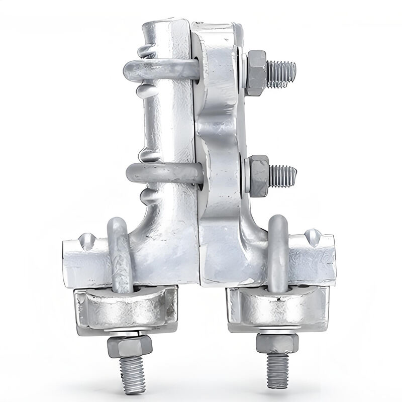
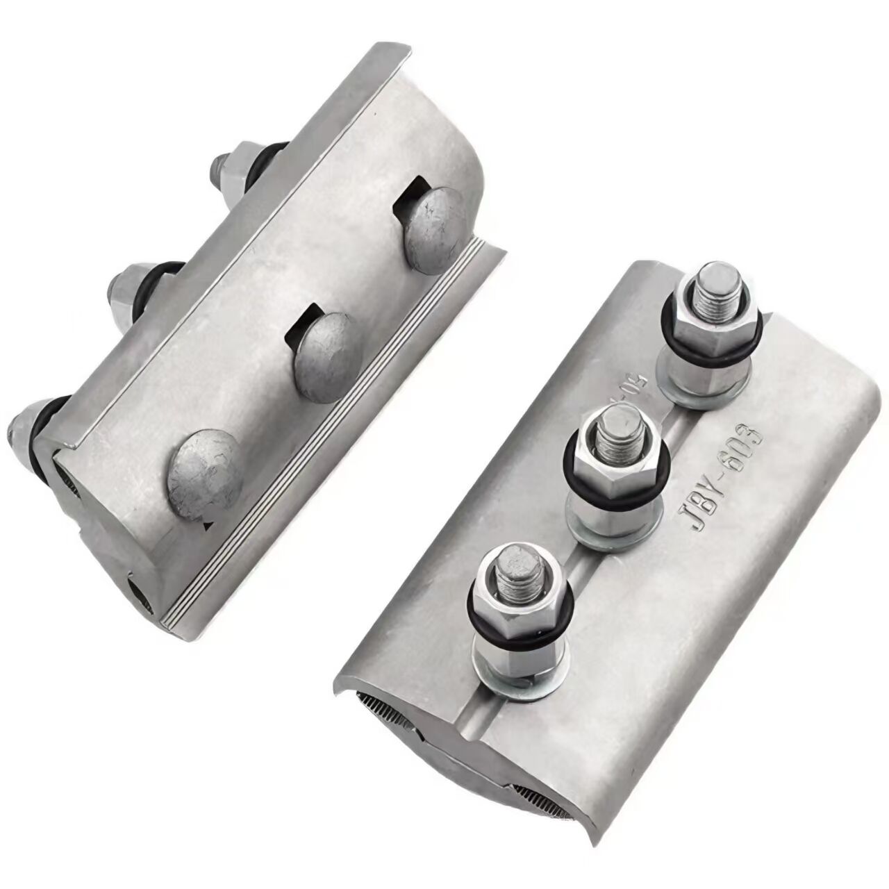
1. Reasonable Structural Design
Composed of a T-shaped base body, main line groove cover, T-shaped upper cover, etc. The horizontal part of the base body is provided with a main line groove, and the vertical part is provided with a branch line hole. The inner wall is equipped with a metal lining that is integrated, and the conductor connection is realized through compression screws.
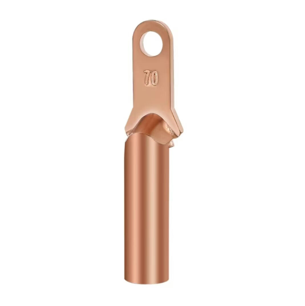
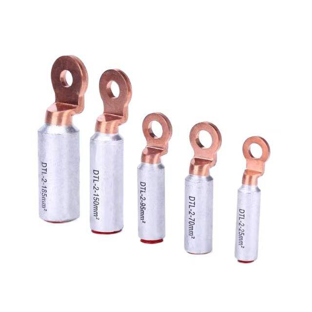
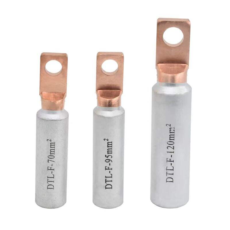
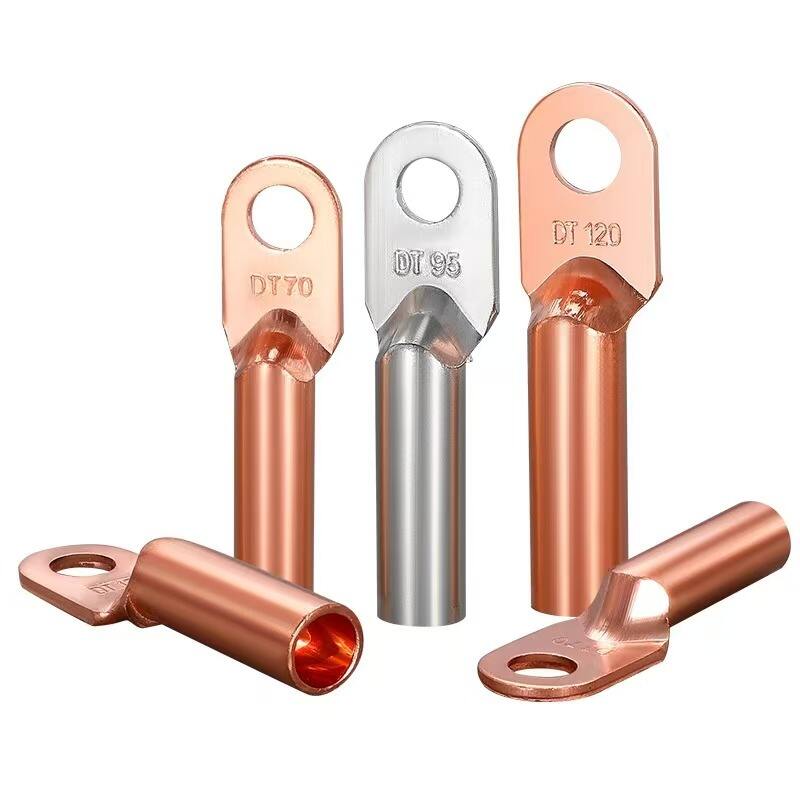
2. High-Quality Materials
Usually made of materials consistent with the wrapped stranded wires, such as copper or aluminum, with strong corrosion resistance.
3. Good Electrical Performance
The branch conductor and main conductor are in close contact with the metal lining through compression screws, with a large contact area. The DC resistance is not greater than that of an equal-length conductor, and the current-carrying temperature rise is lower than that of the conductor. No visible corona occurs under 1.05 times the operating voltage (when the operating voltage is 330KV and above).
4. Stable Grip Strength
The grip strength on the conductor is not less than 10% of the conductor's calculated breaking force. For bolt-type clamps applicable to conductors with a diameter greater than 49mm, the grip strength is not less than 3%.
1. Convenient Installation
Only screw tightening is required for connection, featuring simple operation, time and labor saving. The installation quality is less affected by human factors with good consistency, and no special tools are needed. One person can complete the installation by hand on site.
2. Reliable Operation
The special design avoids the possibility of loss or damage to components such as bolts, nuts, and washers during installation or operation, ensuring reliable operation. Meanwhile, the installation process will not damage the conductor.
TL-T type cable clamps are mainly used in overhead power lines or substations to lead down current branches in a "T" shape on the main line of busbars. They are suitable for connecting leads from main busbars or main circuits to electrical equipment and other circuits, and also for T-junctions when two overhead power lines intersect.
Model | Applicable wire models | All size unit are mm | Weight(kg) | ||||
Bus | Down conductor | Φ1 | Φ2 | H | L | ||
TL-11 | 7.5-9.6 | 7.5-9.6 | 10 | 10 | 102 | 118 | 0.71 |
TL-21 | 10.8-14.0 | 7.5-9.6 | 14 | 10 | 103 | 118 | 0.78 |
TL-22 | 10.8-14.0 | 10.8-14.0 | 14 | 103 | 120 | 0.79 | |
TL-31 | 14.5-17.5 | 7.5-9.6 | 18 | 10 | 117 | 118 | 1.07 |
TL-32 | 14.5-17.5 | 10.8-14.0 | 14 | 120 | 1.06 | ||
TL-33 | 14.5-17.5 | 14.5-17.5 | 18 | 120 | 1.05 | ||
TL-41 | 18.1-22.0 | 7.5-9.6 | 22 | 10 | 118 | 1.13 | |
TL-42 | 18.1-22.0 | 10.8-14.0 | 14 | 120 | 1.13 | ||
TL-43 | 18.1-22.0 | 14.5-17.5 | 18 | 120 | 1.12 | ||
TL-44 | 18.1-22.0 | 18.1-22.0 | 22 | 120 | 1.17 | ||
TL-300/300 | 24.2 | 24.2 | 25 | 25 | 199 | 146 | 3.0 |
TL-400/400 | 28.0 | 28.0 | 28 | 28 | 3.0 | ||
TL-300/185 | 24.2 | 19.0 | 25 | 19 | 168 | 2.6 | |
TL-400/240 | 28.0 | 21.6 | 28 | 22 | 2.6 | ||
TL-300/120 | 24.2 | 15.5 | 25 | 16 | 2.5 | ||
TL-400/150 | 28.0 | 17.2 | 28 | 18 | 2.5 | ||
TL-185/185 | 19.0 | 19,0 | 19 | 19 | 160 | 115 | 2.5 |
TL-240/240 | 21.6 | 21.6 | 22 | 22 | 2.5 | ||
TL-500/500 | 30.2 | 30.2 | 31 | 31 | 199 | 146 | 3.6 |
TL-600/600 | 32.5 | 32.5 | 33 | 33 | 3.6 | ||
All measurements provided are manually obtained and may contain slight tolerances. Final dimensions shall be subject to the physical product. |
Our professional sales team are waiting for your consultation.