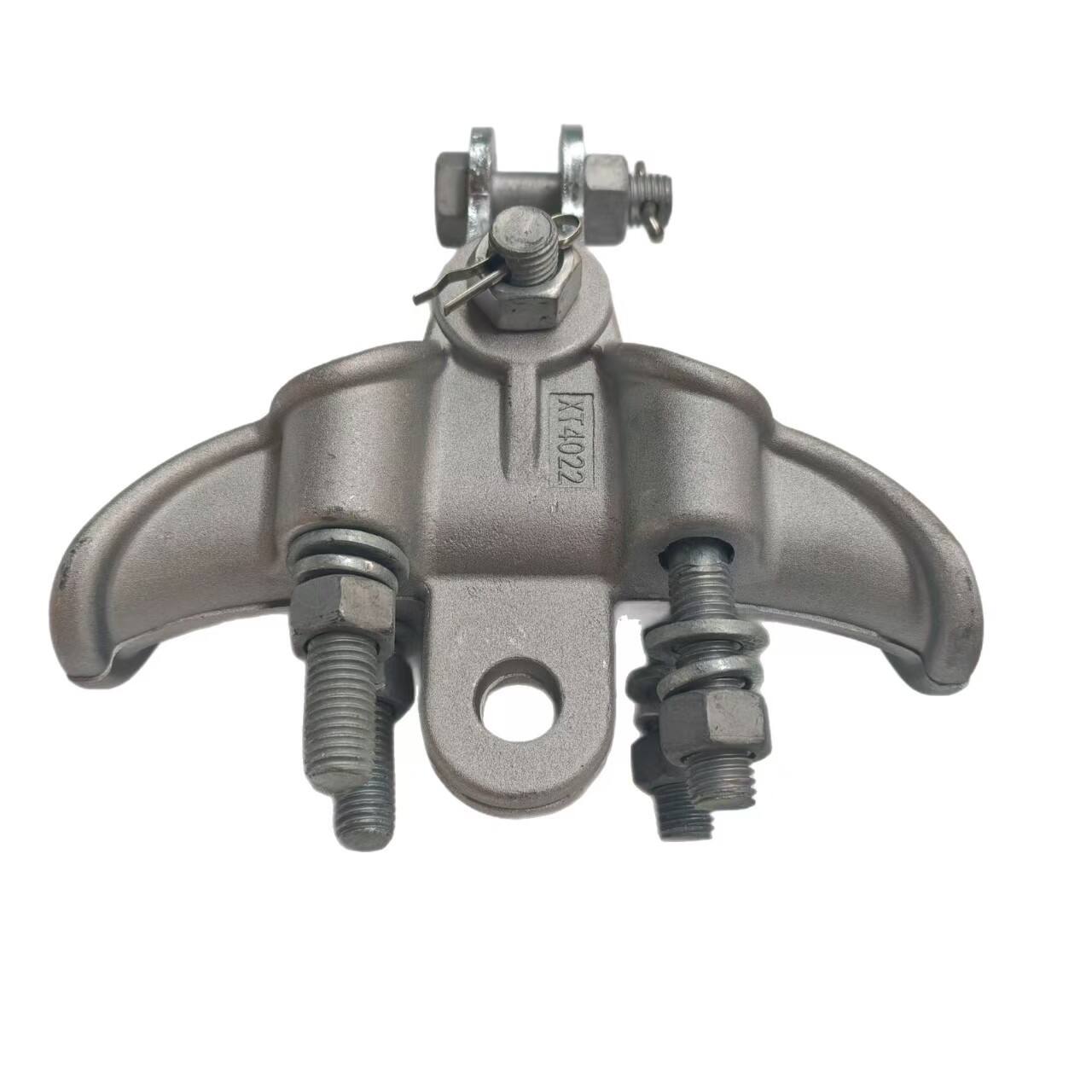
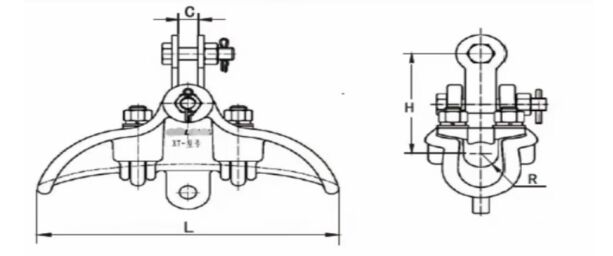
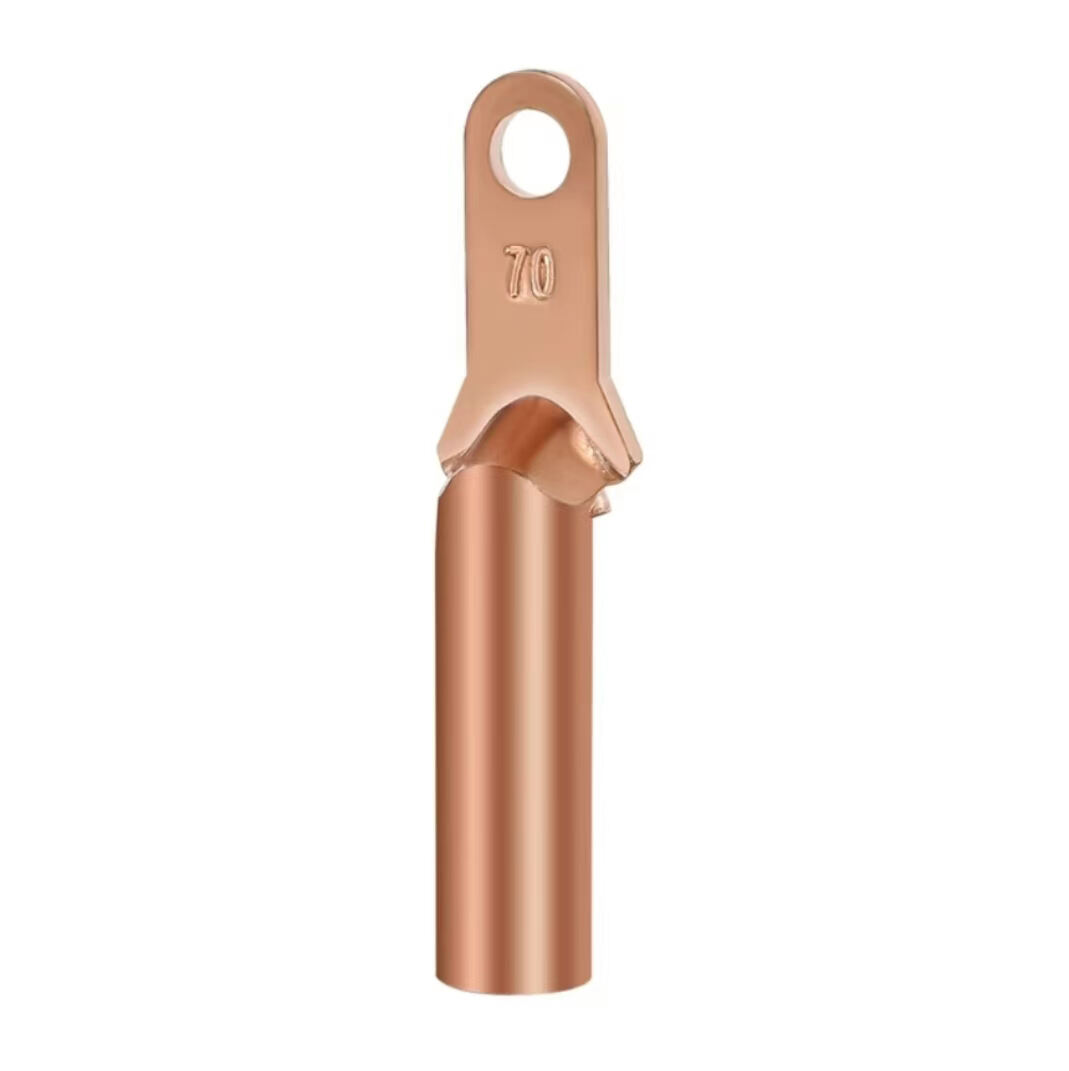
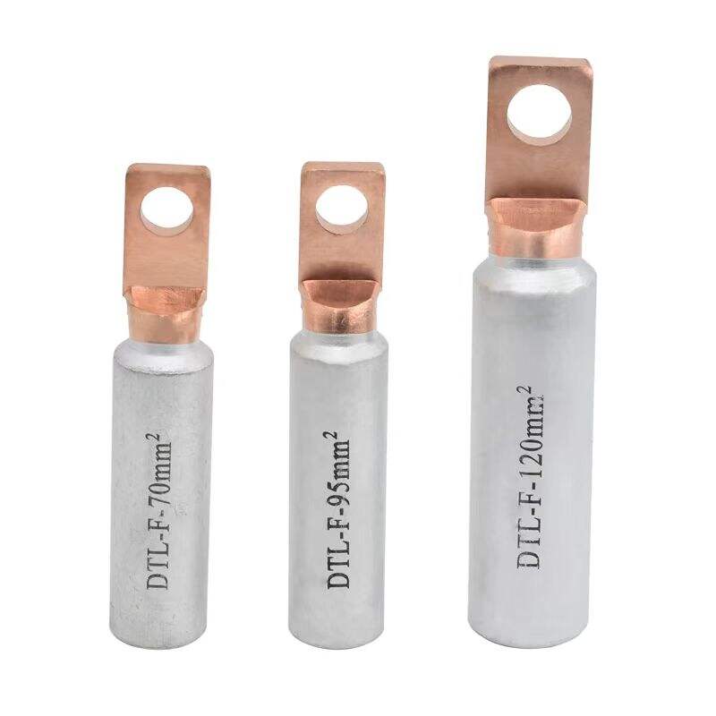
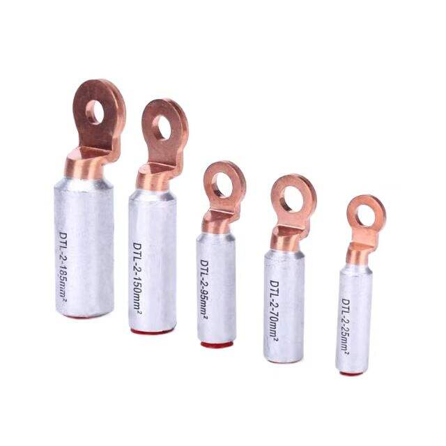
1. High-Quality Materials
Typically manufactured from high-strength aluminum alloy and other premium materials, it features lightweight construction, high strength, and excellent corrosion resistance. This not only effectively reduces the load on utility poles and towers but also adapts to various outdoor environments, significantly extending the service life. The material’s high strength-to-weight ratio ensures reliable mechanical performance while minimizing installation difficulty.
2. Compact Structure
Designed with a compact and space-efficient configuration, it occupies minimal space, facilitating installation in limited or confined areas. This structural advantage makes it ideal for applications in narrow spaces, such as urban power distribution networks or complex tower structures, where traditional clamps may be impractical. Its streamlined design also enhances aesthetic compatibility with different infrastructure setups.
3. Smooth Surface Finish
The clamp body and pressure plate feature smooth surfaces with streamlined edges, which significantly reduce corona discharge—a key factor in power loss. By minimizing corona, the clamp lowers electrical energy dissipation, improves power transmission efficiency, and complies with high-voltage transmission standards. This design also reduces the risk of electrical arcing and associated conductor damage, ensuring long-term reliable operation.
1. Easy Installation
With a rational structural design, it requires no complex tools or special craftsmanship during installation. Construction personnel can complete the installation quickly, effectively reducing construction time and improving work efficiency. This user-friendly design is particularly beneficial for emergency repairs or large-scale grid projects, where time-saving installation can significantly lower labor costs.
2. Reliable Operation
It securely fixes the conductor, preventing displacement, swaying, or detachment during operation to ensure the safe and stable operation of power lines. Additionally, its excellent electrical performance (e.g., low contact resistance, high insulation) reduces the probability of faults such as short circuits or arc discharges, enhancing the reliability of the power system. This dual mechanical and electrical stability makes it suitable for long-term high-load operation in critical power transmission networks.
3. Low Maintenance Cost
Due to its high-quality materials and superior corrosion resistance, it requires no frequent maintenance under normal operating conditions, significantly reducing maintenance costs and workload. The durable construction minimizes the need for replacement or repair, even in harsh environments, thereby lowering the total cost of ownership (TCO) for power utilities. This low-maintenance feature aligns with the requirements of smart grids for high-efficiency asset management.
1. Jumper Fixation
Primarily used to secure jumpers (drain wires) in overhead power lines to insulator strings, ensuring jumpers maintain specified positions and shapes. This meets the installation and operational requirements of electrical equipment by preventing unintended movement and ensuring proper clearances for safe power transmission.
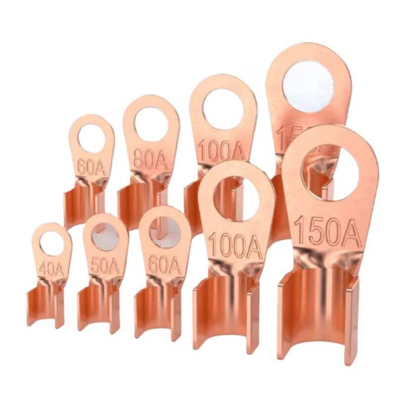
2. Load Bearing
It bears the gravitational force of jumpers, wind load, and other environmental loads, transmitting these forces to utility poles or towers. Engineered to withstand various meteorological conditions (e.g., strong winds, temperature fluctuations), it ensures the safe suspension of jumpers and maintains the mechanical stability of the entire line configuration.
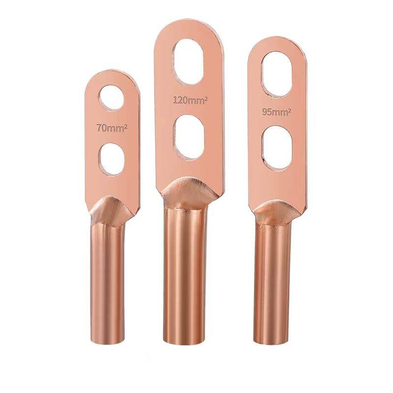
3. Electrical Performance Assurance
Through rational structural design and optimal contact surfaces, it reduces stress concentration at fixation points, protecting jumpers from mechanical damage. Meanwhile, it ensures excellent electrical connectivity between jumpers and insulator strings, minimizing contact resistance and preventing arc discharges. This design guarantees smooth power transmission, complies with high-voltage insulation standards, and enhances the reliability of the electrical system.
Model | Conductordiameter range(Include EntangleMM) | SIZE(MM) | Conductor diameter range(KN) | |||
H | L | R | C | |||
XT-4022 | 13.2~22.0 | 130 | 200 | 11 | 18 | 40 |
XT-4028 | 19.6~28.0 | 138 | 250 | 14 | 18 | 40 |
XT-4034 | 27.4~34.0 | 128 | 300 | 17 | 20 | 40 |
XT-4040 | 32.0~40.0 | 132 | 300 | 20 | 20 | 40 |
XT-6028 | 19.6~28.0 | 138 | 250 | 14 | 18 | 60 |
XT-6034 | 27.4~34.0 | 128 | 300 | 17 | 20 | 60 |
XT-6040 | 32.0~40.0 | 132 | 300 | 20 | 20 | 60 |
All measurements provided are manually obtained and may contain slight tolerances. Final dimensions shall be subject to the physical product. |
Our professional sales team are waiting for your consultation.