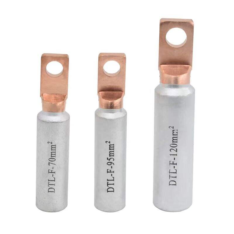
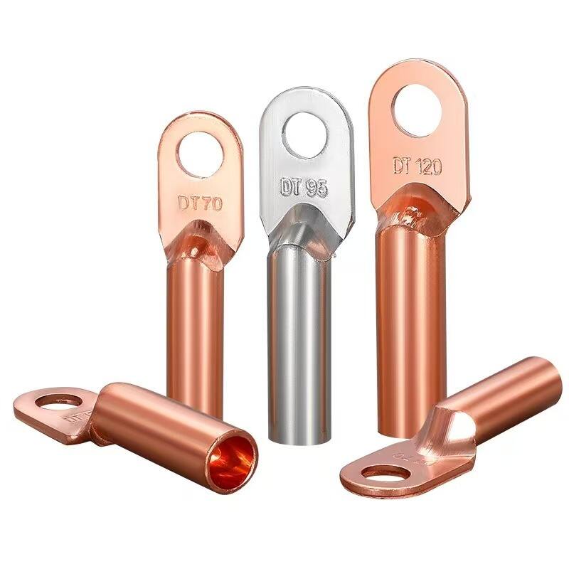
1. Special Material Composition
Some types are manufactured using copper-aluminum composite metal strips, with a copper-aluminum bonding strength ≥100MPa. This design combines the excellent electrical conductivity of copper with the lightweight and corrosion-resistant properties of aluminum, making it ideal for high-current transmission scenarios while reducing structural weight and enhancing environmental adaptability.
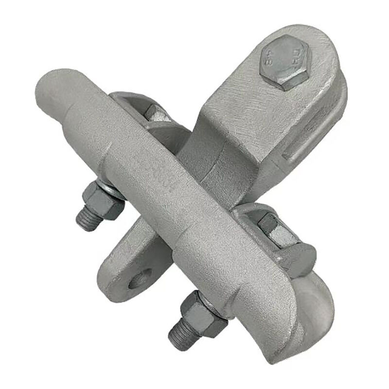
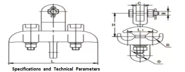
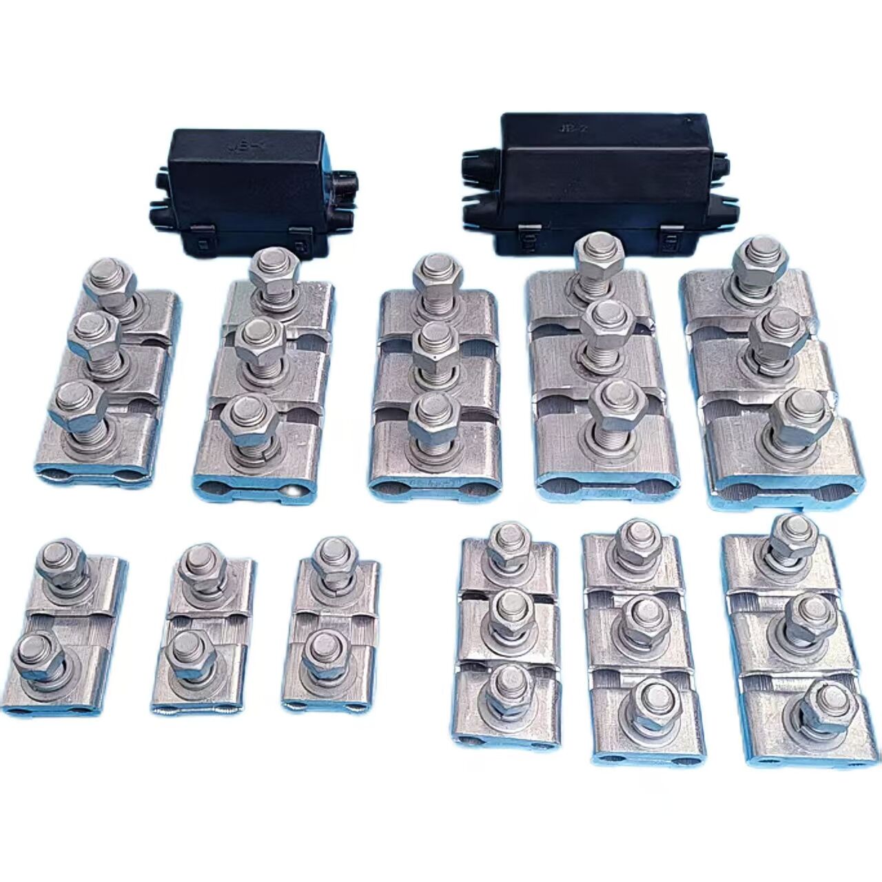
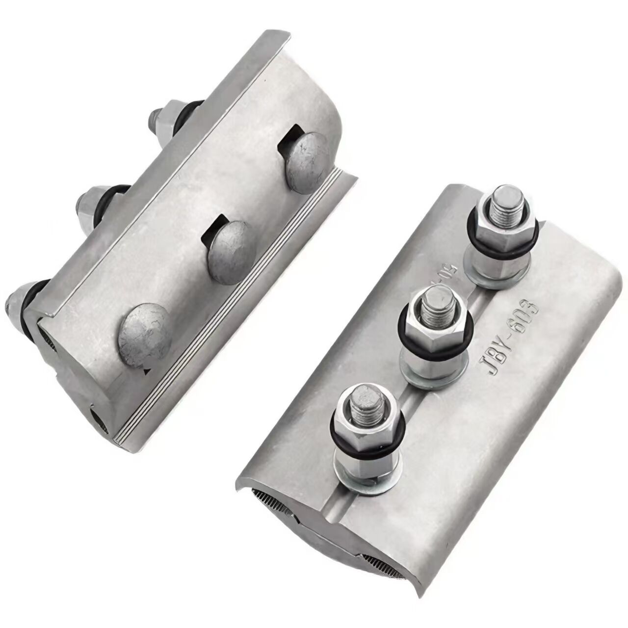
2. Structural Design
Typically consists of a conductor-carrying plate, pressure block, suspension assembly, and fasteners:
The conductor-carrying plate and pressure block are equipped with two wire grooves, separated by a flat surface and through-holes.
Wires are fixed via fasteners through the through-holes, ensuring secure clamping.
The suspension assembly is centrally positioned on the flat surface between the two wire grooves of the conductor-carrying plate, providing balanced mechanical support and precise alignment for overhead installation.
3. Low Resistance and Heat Generation
For example, the XTS suspension clamp using copper-aluminum composite metal strips exhibits lower electrical resistance and heat generation compared to traditional aluminum alloy or ferromagnetic products. This reduces power loss during transmission—tests show a 15-20% reduction in energy dissipation under rated load—thereby improving transmission efficiency and minimizing thermal stress on conductors and equipment
1. Excellent Energy-Saving Performance
Due to its low electrical resistance and heat generation characteristics, it reduces energy consumption in transmission lines, achieving energy conservation and environmental protection. This is particularly suitable for transmission scenarios with strict requirements for power loss, such as high-voltage and extra-high-voltage transmission lines, where it can significantly improve overall system efficiency.
2. Convenient Installation
With a rational structural design, the installation process is relatively simple, requiring no complex tools or special craftsmanship. Construction personnel can complete the installation quickly, effectively reducing construction time and improving work efficiency. This feature is highly beneficial for both new grid construction and maintenance projects, minimizing labor costs and project delays.
3. Wide Application Range
As a type of line fitting, it is widely used for fixing twin-conductor jumpers in overhead power lines. It is suitable for overhead transmission lines of different voltage classes demonstrating strong adaptability to various grid structures. Its versatility makes it an ideal choice for urban power networks, rural distribution lines, and long-distance transmission projects.
1. Jumper Fixation
Primarily used in overhead power lines to secure twin-conductor jumpers to insulator strings or utility poles/towers, ensuring jumpers maintain specified positions and shapes. This meets the installation and operational requirements of electrical equipment by preventing displacement and ensuring proper clearances for safe power transmission.
2. Load Transfer
It bears the gravitational force of jumpers, wind load, and other environmental loads, transmitting these forces to utility poles/towers or insulator strings. Designed to withstand various meteorological conditions it ensures the safe suspension of jumpers and maintains the mechanical stability of the overhead line system.
3. Electrical Connection
Through optimized contact design, it ensures excellent electrical connectivity between jumpers and other electrical equipment, minimizing contact resistance. This reduces heat generation and discharge issues caused by poor connections, guarantees smooth power transmission, and complies with high-voltage insulation and conductivity standards.
SG Model | Equivalent Model | Conductor diameter range(Include EntangleMM) | SIZE(mm) | Maximum load capacity (KN) | |||||
Φ | R | L | M | C | H | ||||
XTS-4028 | XTS-2B | 18 | 14 | 200 | 16 | 20 | 77 | 40 | |
XTS-4034 | XTS-2 | 18 | 17 | 200 | 16 | 20 | 81 | 40 | |
XTS-2C | 18 | 20 | 250 | 16 | 20 | 103 | 40 | ||
XTS-6022 | 18 | 13 | 200 | 16 | 20 | 77 | 60 | ||
XTS-6028 | 22.0~27.0 | 18 | 14 | 200 | 16 | 20 | 77 | 60 | |
XTS-6034 | XTS-5 | 27.0~33.0 | 18 | 17 | 200 | 16 | 20 | 81 | 60 |
XTS-6040 | 32.0~39.0 | 18 | 20 | 250 | 16 | 20 | 103 | 60 | |
XTS-6 | 34.0~45.0 | 18 | 23 | 250 | 16 | 20 | 103 | 70 | |
All measurements provided are manually obtained and may contain slight tolerances. Final dimensions shall be subject to the physical product. |
Our professional sales team are waiting for your consultation.