1. Structural Design
Adopts a wedge-shaped structure, composed of a clamp body made of malleable cast iron and a wedge. The steel strand is bent into the same shape as the wedge and installed in the clamp.
2. Material and Anti-Corrosion
Typically hot-dip galvanized, offering excellent anti-corrosion performance to adapt to harsh outdoor environments and extend service life.
3. Working Principle
Utilizes the splitting force of the wedge. When the steel strand is under tension, the wedge and steel strand simultaneously slide along the inner wall of the clamp barrel toward the outlet, tightening progressively and gradually achieving a locked state.
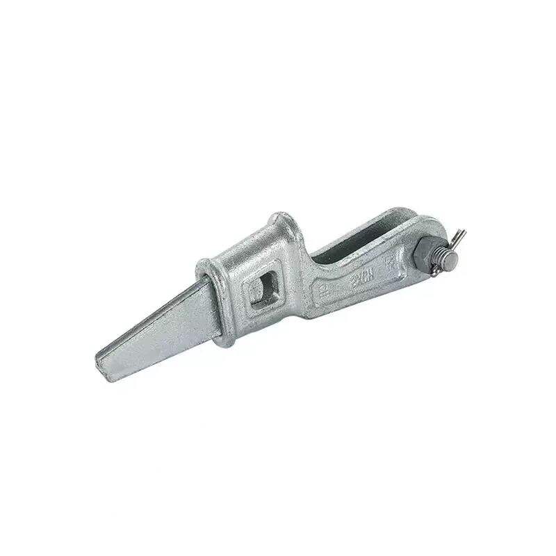
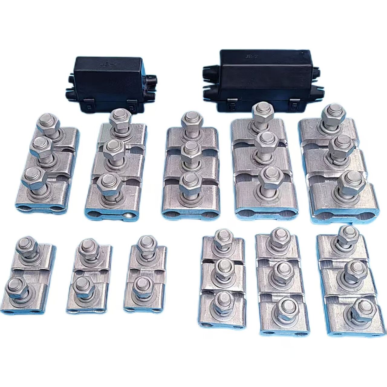
1. Convenient Installation
The installation process is simple: just bend the steel strand as required and place it into the clamp, requiring no complex tools or procedures. Once installed, it is secure and unlikely to loosen.
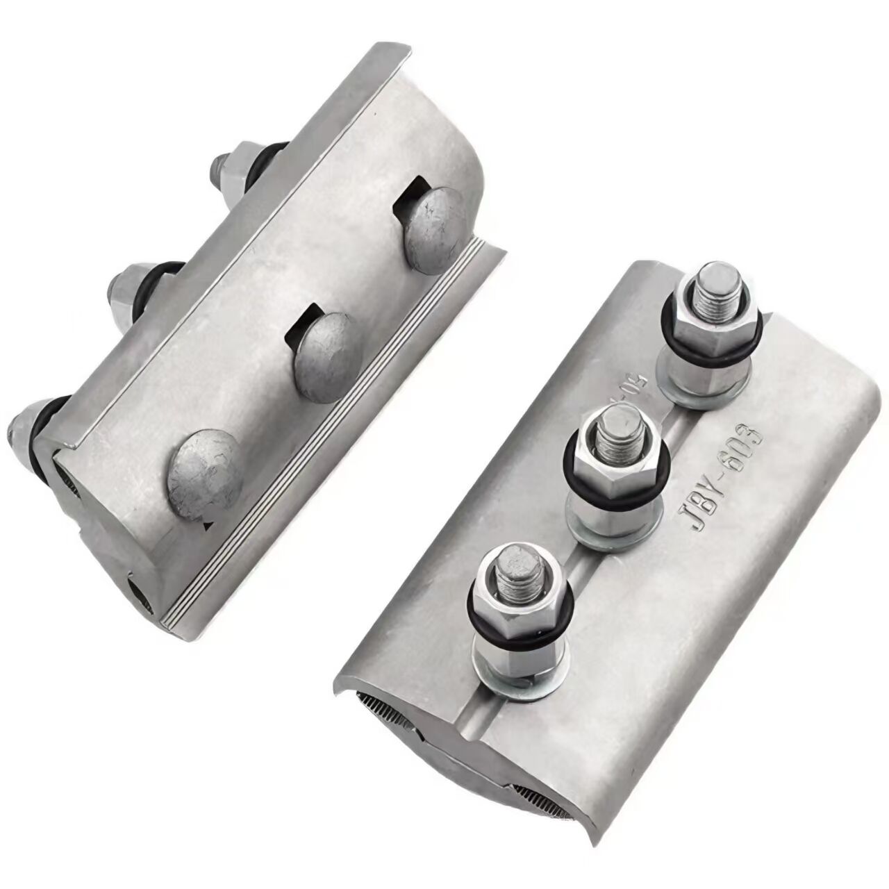
2. Excellent Self-Locking Performance
Features a strong self-locking function: as the tension on the steel strand increases, the friction between the wedge and the strand also increases, ensuring a firm clamping effect and high safety.
3. Wide Application Range
Can be used for installing steel strands, fastening overhead ground wires, and securing guy wires on guyed towers. It is also commonly used with UT-type clamps to fix conductors or overhead ground wires to the tension insulator strings of non-straight towers.
1. Tightening and Anchoring
Mainly used to fasten steel strands, overhead ground wires, etc., to towers or other structures for anchoring, ensuring line stability and preventing conductors or ground wires from shifting or falling off due to external forces.
2. Connection Function
In power lines, it acts as a connecting component to link the guy wires of guyed towers with the towers, or to connect tension insulator strings with conductors or overhead ground wires, forming a complete power transmission system.
3. Auxiliary Positioning
Helps determine the position of conductors or overhead ground wires, making the line layout more standardized and tidy, and facilitating construction and maintenance.
CatalogNo. | SteelWire Dia.(MM) | ALL SIZE(MM) | RatedFailure Load(KN) | Weight(kg) | |||
C | M | L | R | ||||
NX-1 | 6.6~7.8 | 18 | 16 | 150 | 6.0 | 45 | 1.20 |
NX-2 | 9.0~11.0 | 20 | 18 | 180 | 7.3 | 88 | 1.76 |
NX-3 | 13.0~14.0 | 25 | 24 | 195 | 8.0 | 143 | 3.20 |
NX-4 | 15.0~16.0 | 30 | 27 | 220 | 8.0 | 164 | 4.60 |
All measurements provided are manually obtained and may contain slight tolerances. Final dimensions shall be subject to the physical product. |
Our professional sales team are waiting for your consultation.